Schematic block diagram of a fluorometer Diode array versus filter-based spectrometers Schematic of the double-pulse laser fluorometer used to perform the
B for Biology: Spectrophotometry - Spectrofluorimetry Part 1
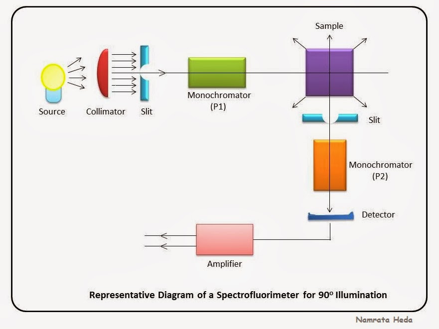
Schematic block diagram of a fluorometer Fluorometer : principle (fluorometry), types, diagrams and applications Fluorometer schematic chapter ppt powerpoint presentation fluorescence
Fluorometer pulse perform experiments
Spectrometer diagram spectrofluorometer photoluminescence edinburgh instrumentsSchematic diagram of the fluoromap fluorometer (a) and close-up of the Fluorescence sensorsFluorometer block diagram.
2 : schematic representation of a typical fluorescence spectrometerSchematic block diagram of a fluorometer B for biology: spectrophotometryFluorometer assignment.

Fluorometer arrangement
Fluorometer fluorescence molecular libretexts emission excitation chemDiy fluorometer for dna concentration Fluorescence instrumentation spectrofluorometer spectroscopy fluorescent cuvette passesBlog posts archive.
Fluorometer fluorescence tryptophan methods aggregation spectroscopic intensity signalSpectrofluorometer diagram instrument optical theory draw applications pharmaceutical give its adsense Fluorescence spectrometerPart spectrophotometry components following different.

Instrumentation of fluorescence spectroscopy ( spectrofluorometer ) and
Draw an optical diagram of spectrofluorometer, give its theory andSchematic diagram of fluorometer arrangement for real time monitoring Citizen science/open fluorometer projectSchematic diagram of spectrophotometer.
A schematic diagram of the fluorometer used for the assignment of mesfSolved: draw a schematic diagram of a fluorometer and name its main Schematic setup of the modules of the fluorometer prototypesFluorometer block diagram.

Schematic of the fluorometer.
A schematic diagram of the fluorometer used for the assignment of mesfFluorometer fluorometric quantification principle working rna via Fluorometer fluorescence openwetware citizenFluorometer valeport hyperion fluorimeter datchiki perpendicular excited detector.
The working principle of a fluorometer4 schematic diagram of a fluorescence spectrometer. Fluorescence spectrometer schematic representation typicalFluorescence spectrometry scheme.

Lab 4: molecular fluorescence
Schematic diagram of fluorescence spectrophotometer » circuit diagramFluorometer dna concentration diy physicsopenlab Fluorometer fluorescence spectroscopy diagram, png, 1440x849px(a) schematic representation of a fluorometer instrument. (b.
Fluorometer concentration physicsopenlabFluorometer diagram schematic phase figure Fluorescence spectrometry.

B for Biology: Spectrophotometry - Spectrofluorimetry Part 1

Diode array versus filter-based spectrometers - Ibsen Photonics

Draw an optical diagram of spectrofluorometer, Give its theory and

Lab 4: Molecular Fluorescence - Chemistry LibreTexts

Schematic of the Fluorometer. | Download Scientific Diagram

Schematic Block Diagram Of A Fluorometer - Circuit Diagram

Fluorometer Fluorescence Spectroscopy Diagram, PNG, 1440x849px
